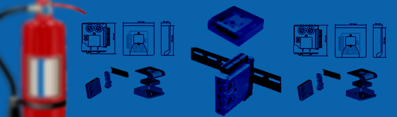
Four different monitor modules are available for Fire•Lite’s intelligent control panels to suit a variety of applications. Monitor modules are used to supervise a circuit of dry-contact input devices, such as conventional heat detectors and pull stations, or monitor and power a circuit of two-wire smoke detectors (MMF-302(A)). MMF-300(A) is a standard-sized module (typically mounts to a 4" [10.16 cm] square box) that supervises either a Style D (Class A) or Style B (Class B) circuit of dry-contact input devices. MMF-301(A) is a miniature monitor module a mere 1.3" (3.302 cm) H x 2.75" (6.985 cm) W x 0.65" (1.651 cm) D that supervises a Style B (Class B) circuit of dry-contact input devices. Its compact design allows the MMF-301(A) to be mounted in a single-gang box behind the device it monitors. MMF-302(A) is a standard-sized module used to monitor and supervise compatible two-wire, 24 volt, smoke detectors on a Style D (Class A) or Style B (Class B) circuit. MDF-300(A) is a standard-sized dual monitor module used to monitor and supervise two independent two-wire Style B (Class B) dry-contact initiating device circuits (IDCs) at two separate, consecutive addresses in intelligent, two-wire systems
MMF-300(A), MMF-302(A), and MDF-300(A) modules mount directly to a standard 4" (10.16 cm) square, 2.125" (5.398 cm) deep, electrical box. They may also be mounted to the SMB500 surface-mount box. Mounting hardware and installation instructions are provided with each module. All wiring must conform to applicable local codes, ordinances, and regulations. These modules are intended for power-limited wiring only. The MMF-301(A) module is intended to be wired and mounted without rigid connections inside a standard electrical box. All wiring must conform to applicable local codes, ordinances, and regulations.
The MMF-300(A) Monitor Module is intended for use in intelligent, two-wire systems, where the individual address of each module is selected using the built-in rotary switches. It provides either a two-wire or four-wire fault-tolerant Initiating Device Circuit (IDC) for normally-open-contact fire alarm and supervisory devices. The module has a panel-controlled LED indicator. The MMF-300(A) can be used to replace M300(A) modules in existing systems. Use to monitor a zone of four-wire smoke detectors, manual fire alarm pull stations, waterflow devices, or other normallyopen dry-contact alarm activation devices. May also be used to monitor normally-open supervisory devices with special supervisory indication at the control panel. Monitored circuit may be wired as an NFPA Style B (Class B) or Style D (Class A) Initiating Device Circuit. A 47K Ohm End-of-Line Resistor (provided) terminates the Style B circuit. No resistor is required for supervision of the Style D circuit.
The MMF-302(A) Interface Module is intended for use in intelligent, addressable systems, where the individual address of each module is selected using built-in rotary switches. This module allows intelligent panels to interface and monitor twowire conventional smoke detectors. It transmits the status (normal, open, or alarm) of one full zone of conventional detectors back to the control panel. All two-wire detectors being monitored must be UL compatible with the module. The MMF-302(A) can be used to replace M302(A) modules in existing systems.Use the MMF-302(A) to monitor a zone of two-wire smoke detectors. The monitored circuit may be wired as an NFPA Style B (Class B) or Style D (Class A) Initiating Device Circuit. A 3.9 K Ohm End-of-Line Resistor (provided) terminates the end of the Style B or D (class B or A) circuit (maximum IDC loop resistance is 25 Ohms). Install ELR across terminals 8 and 9 for Style D application.